
Mick Reeves 1/6 Scale Spitfire Review
|
 |
 |
 |
 |
| 1. Click to enlarge | 2. Click to enlarge | 3. Click to enlarge | 4. Click to enlarge |
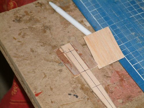
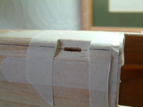
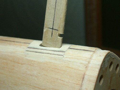
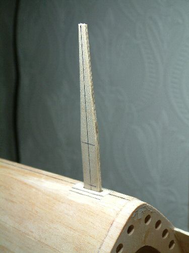
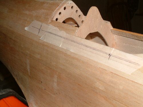
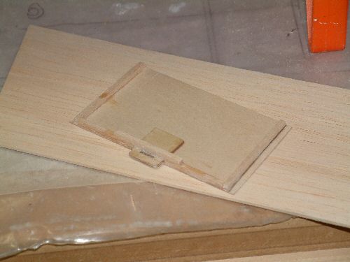
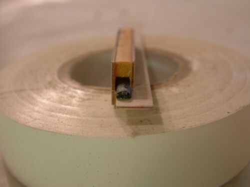
| Before starting on the main cockpit area I installed the support for the antenna mast as access to this area will become restricted later. I am designing the mast so it can be easily installed and removed to protect it from damage. Pic 1. The antenna mast was cut from 3mm ply and notched at the bottom. A sleeve was fabricated from balsa and light ply for it to slide into with a corresponding tab installed into the sleeve for the antenna mast to locate into. This will make a simple lock for the mast which will be prevented from falling out in flight because of the tension of the aerial (that was my idea!). The picture shows the sleeve before the side is fixed, with the position of the locating tab shown. Pic 2. A small section was cut from the top of the fuse to accept a ply strengthener later. A slot was cut for the mast to pass through. The sleeve installs directly underneath with a supporting cross beam glued in position. I was particularly careful to ensure the mast was vertical and in alignments with the fin as it was drying. When dry a small section of ply was installed into the groove to add some durability to the installation and a firm point for the mast to rest against. Pic 3. Basically the mast slides in tipped slightly forwards as shown in the picture and locates in the notch when pulled back. Pic 4. The final resting place for the mast - fantastically simple! |
 |
 |
 |
 |
 |
 |
| 1. Click to enlarge | 2. Click to enlarge | 3. Click to enlarge | 4. Click to enlarge | 5. Click to enlarge | 6. Click to enlarge |
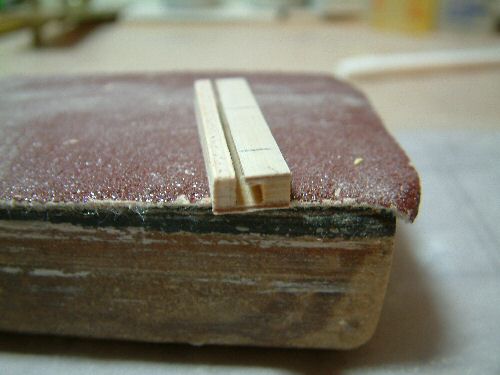
| Pic 1. Time to get on with the cockpit area. First off I loose fitted the canopy parts and marked the position of the bottom edge of the sliding canopy. Then extended the line to cover the full travel of the cockpit. Pic 2. sliding channel made from 1/8" spruce, 1/8" light ply, and 1/32" ply held together with Cyano. Pic 3. Channels were carved out of the fuse sides 180mm long to accept the sliders, before fixing in position with PVA. Pic 4. A 1/64" ply lining was applied in the upper half of the cockpit to improve the general appearance. I then gave the interior of the cockpit a coat of suitable green paint. Pic 5. The floor for the rear cockpit is also fabricated from 1/32" ply and designed to be detachable. It rests on the stringers and has some supports applied to hold it in position. The slot at the front will locate in a hook on the back of the pilots seat (see later). This holds the rear cockpit floor in position and a good fixing point for the seat. Pic 6. The rear cockpit floor in position and ready to hook up to the seat. Also visible is the heel plate in the bottom which is installed centrally by 4 screws in hardwood supports. |
 |
 |
 |
 |
 |
| 1. Click to enlarge | 2. Click to enlarge | 3. Click to enlarge | 4. Click to enlarge | 5. Click to enlarge |
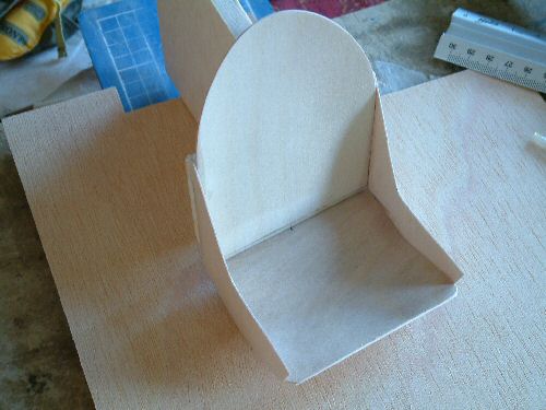
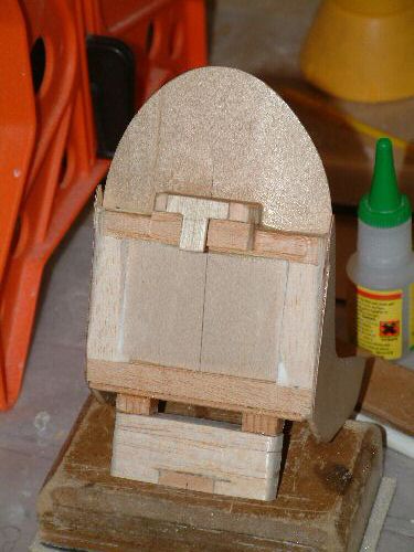
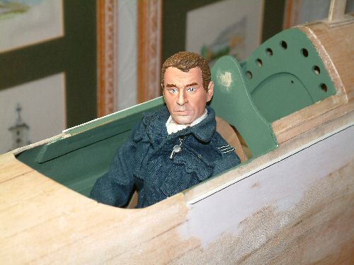
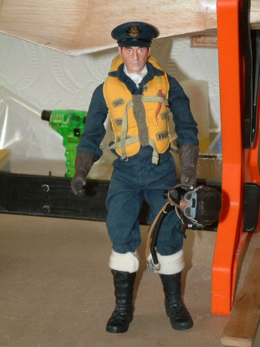
Pic 1. The seat is a simple fabrication from 1/32" ply from the drawings on the plans. The seat will be removable for access should it be required. Pic 2. The seat has a hook added to the back to locate in the rear cockpit floor sheet, and is shimmed for installation on the heel plat at the bottom. Pic 3. Shows the seat in position with the pilot testing out the seat. If the pilot ends up sitting too low in the cockpit I will pad out the seat a little. That will be determined later. Pic 4. A length of shoe lace stained with tea to make it off white was used to build the upper part of the seat belt harness, and retained by a short length of wire in the rear cockpit area. Pic 5. While we're on the subject of the Pilot I am using an Elite Force WWII RAF Fighter Pilot purchased from eBay. Reasonably realistic for what I want. |
 |
 |
 |
 |
 |
| 1. Click to enlarge | 2. Click to enlarge | 3. Click to enlarge | 4. Click to enlarge | 5. Click to enlarge |
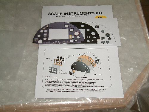
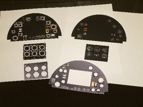
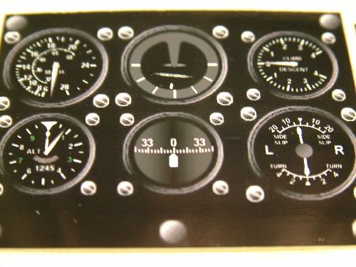
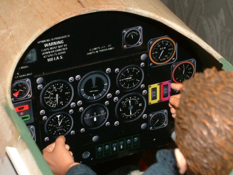
I am not going to get too carried away with detail in the cockpit but the basics will be there, dials, seat, control stick, some trim, and a pilot. Pic 2. Shows a comparison of my creation and the originals. These are an earlier design designed to fit in the supplied kit. Pic 3. A close up of the final version of the dials in flat 2D. The main centre dials will remain mounted on a separate sheet of wood to give a little 3D effect. Pic 4. The complete instrument panel finally in position. The images were printed onto photo paper and then glued with a little PVA onto the wood pieces. The smaller centre panel was put into position with double sided sticky tape. Pic 5. From the rear of the instrument panel a fixing using a block of softwood and a rubber band are used to retain the dials in position. If they ever get damaged, or I change my mind over the design, it is a simple matter to replace the unit. |
 |
 |
 |
 |
 |
 |
| 1. Click to enlarge | 2. Click to enlarge | 3. Click to enlarge | 4. Click to enlarge | 5. Click to enlarge | 6. Click to enlarge |
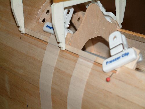
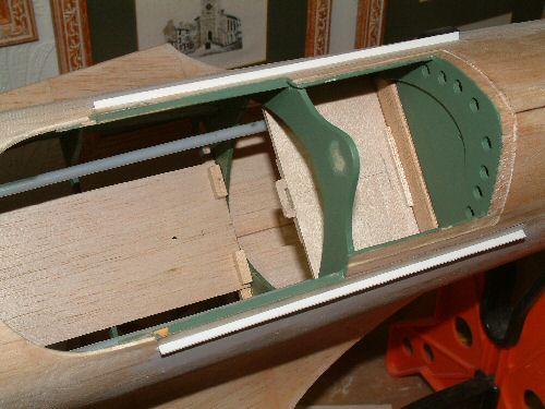
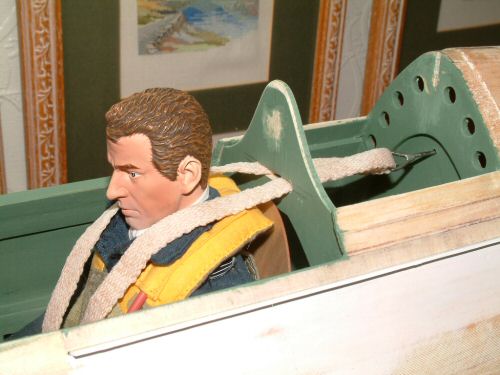
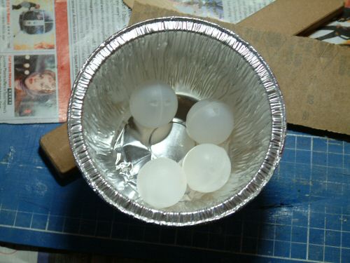
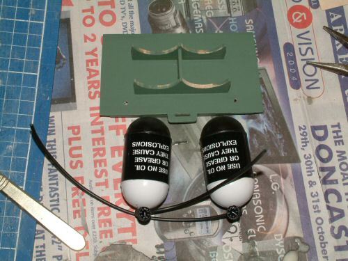
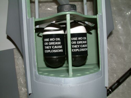
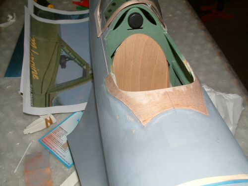
There is not much information about the contents of the rear canopy space behind the pilot. Some pictures I have from MK IXc's have 2 oxygen bottles situated behind the seat. I decided to have a go at re-creating these tanks. Pic 1. A necessary component was the acquisition of 4 gas "widgets" from Draught Guinness cans which are just the right diameter for the tanks (30mm). It is strongly recommended that you do not drink 4 cans of Guinness before continuing your build as you could injure yourself or even worse the Spitfire! I painted 2 balls white and the other 2 black. The cylinder of the bottles are made from 220gsm inkjet paper with the warning text printed on the side with a stenciled font (this text is correct for the period). Pic 2. I added some pressure gauges for a touch of realism with some connecting hoses. The cylinders were then mounted on supports built into the base plate for the rear cockpit. Pic 3. All installed in position. Pic 4. The rear cockpit canopy was cut from flat stock sheet rather than the pre-formed supplied part which did not conform to shape very well. This way I had control of the proceedings. To make the fit good I carefully cut a small bridge from 1/32" ply sheet to support the canopy in position at the front end. That done I scuffed & drilled a few holes on the frame and also scuffed the surfaces of the plastic sheet with course sandpaper. I used Formula 560 Canopy glue to hold the canopy in position. Pic 5. The canopy frame was edged with 1/64" ply. This picture showing the rear and front edge strip in position. I also test fitted the canopy cut to hold the sliding beams made from a section of 1/32" ply. Pic 6. Lower frame now in position and filler in behind canopy frame to feather away the small ridge. A test fit of the font canopy is not looking too good as it is not sitting on the fuse and meeting the canopy correctly. Alternative action may be needed here! |
 |
 |
 |
 |
 |
 |
| 1. Click to enlarge | 2. Click to enlarge | 3. Click to enlarge | 4. Click to enlarge | 5. Click to enlarge | 6. Click to enlarge |
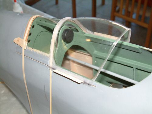
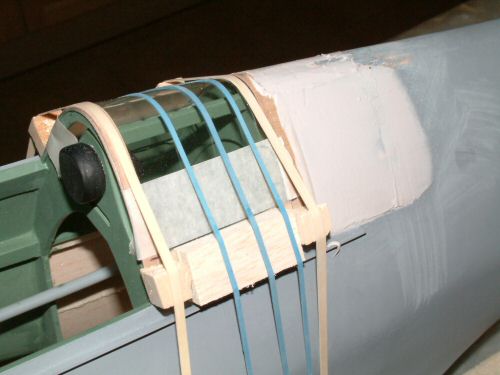
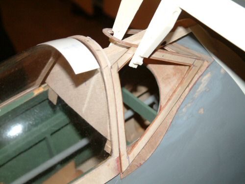
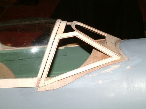
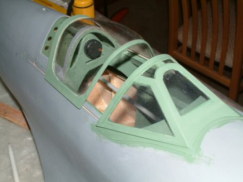
Pic 1. The sliding canopy has its sliding mounts sandwiched between 2 strips of 1/32" ply and allowed to dry thoroughly. Pic 2. Test fitted in the runners the canopy looks OK. Picture also shows the filler sanded down and the canopy taped over ready to receive a few primer coats. Pic 3. Spare channeling from the fuselage and the small tabs cut from carbon rod split in half before epoxying to the canopy slide runners. In testing this provides plenty of support to hold the canopy in position. Pic 4. shows the installed canopy. Note the small tabs to the rear of the channels to permit entry of the canopy. With 2 light coats of primer the job looks good so far. Pic 5. As I suspected earlier the front fixed canopy does not fit properly without hacking away at the bottom of the front section. This will look very wrong. I have therefore decided to fabricate my own! Here the lower apron installed made from 1/32" ply using the original cockpit as a template. Pic 6. Sections fitting together carefully cut from 1/32" ply and lined with 1/64" ply to laminate the panels against. Inside the cockpit is a temporally installed former to hold the shape of the cockpit during construction. |
 |
 |
 |
 |
| 1. Click to enlarge | 2. Click to enlarge | 3. Click to enlarge | 4. Click to enlarge |
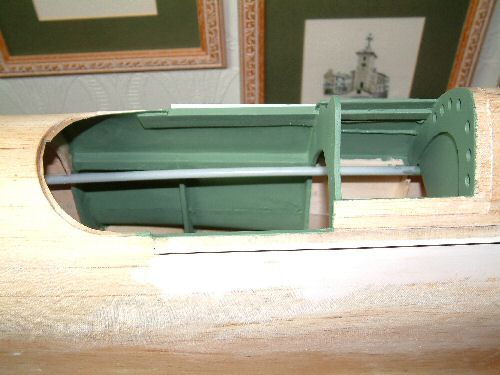
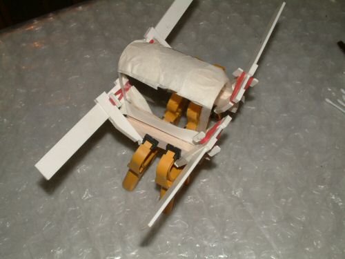
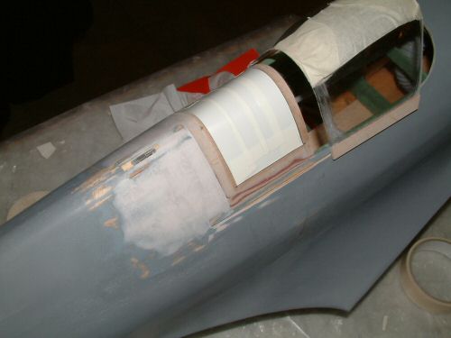
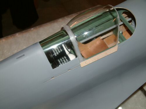
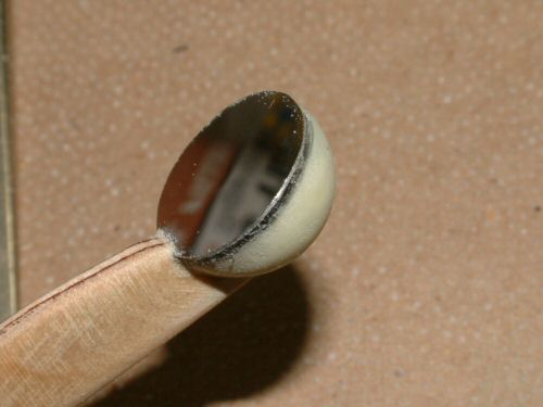
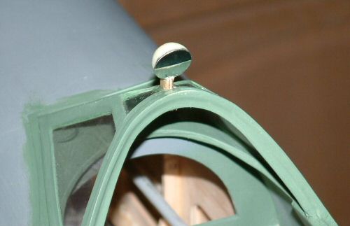
Pic 1. First stage complete now. Picture shows the slightly inset 1/64" ply to hold the clear sheet in position. Once installed there is another skin of 1/64" ply to install over the whole outer surface to finish the job. Pic 2. Plastic sheet installed and the outer 1/64" ply installed. Pictured here after the first sealing coat of paint has been applied. Generally I am happy with the result. Pic 3. The rear view mirror is made from an Epoxy and Microballoons mix, molded in a small plastic ball which was discarded when set. I hollowed it out sufficient to accept a ply post. The hollow was filled in with Epoxy and the polished steel mirror installed. Pic 4. A slot was carefully made in the frame to accept the post and installed with Epoxy onto a ply former underneath. A little sanding and filling around the mirror will be required for the final result before painting. |