
Mick Reeves 1/6 Scale Spitfire Review |
 |
The wood fuselage was not my first choice of construction. With the kit I ordered a Glass fuselage and ran into difficulties with the construction because of serious deformation of the glass structure. A record of the build with the Glass fuselage can be viewed by clicking here. |
Wood Fuselage Construction begins
|
|
 |
 |
 |
 |
 |
 |
| 1. Click to enlarge | 2. Click to enlarge | 3. Click to enlarge | 4. Click to enlarge | 5. Click to enlarge | 6. Click to enlarge |
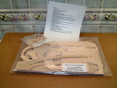
The new wood fuselage parts have arrived. Pic 1. What you get. CNC cut parts easily identified and can be prepared for assembly in an hour. Not so sure about the Fin parts as they remind me of the stabiliser, elevator and rudder fabrication, although I have to admit the wood is much stronger. A sheet of A4 instructions are provided with a suggested building order. The glass cowl has not been supplied yet due to Mick not having any stock. Should be with me in 2-3 weeks. On with the build! Pic 2. A few things to be wary of at this point.
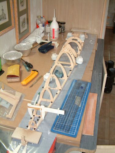
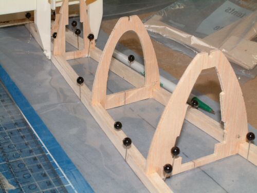
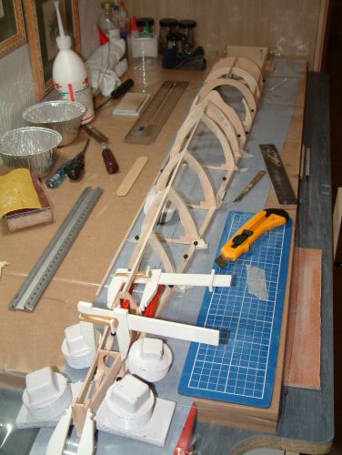
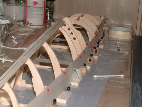
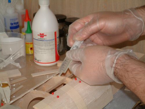
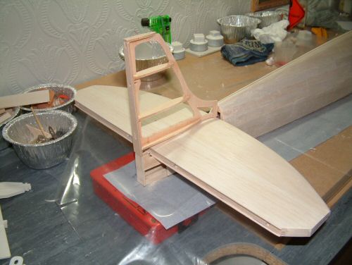
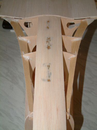
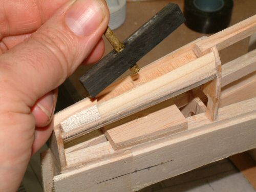
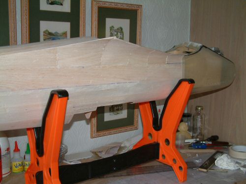
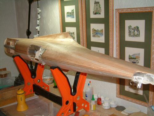
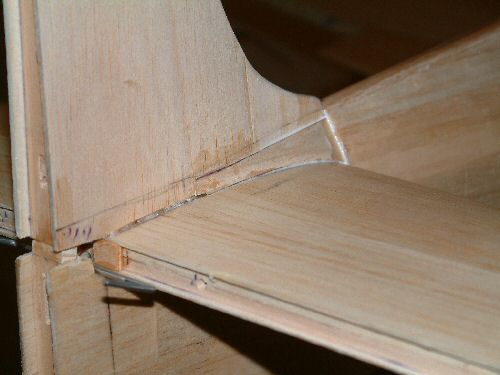
Next stage once the glue had dried was to install the front brace former F8, which required a little sanding to make it fit, followed by the tail supports and spine stripes. Another drying period was required. The instructions describe a method for applying a 4" full length sheet of balsa to the fuselage in one go. I attempted this but was not happy with the way the installation was going and abandoned the installation. I removed the strip and cleaned up the formers etc. Instead of the single sheet I adopted a method applying narrow planks to the formers. Pic 5. shows the beginning of this process, slightly larger width for the first relatively straight surfaces, then using several narrower lengths until the whole top surface was covered. I took some time to consider where the canopy would fit and to ensure there was plenty of excess sheeting to trim back later. Pic 6. shows application of a Thixotropic Polyurethane wood glue to the joining surfaces of the planks. I use this adhesive because it is very strong and foams slightly when curing. This helps to fill the small gaps that exist between the wood strips. The glue is mildly irritant and impossible to get off the skin hence the gloves (honest!).
|
 |
 |
 |
 |
 |
 |
| 1. Click to enlarge | 2. Click to enlarge | 3. Click to enlarge | 4. Click to enlarge | 5. Click to enlarge | 6. Click to enlarge |
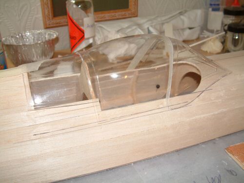
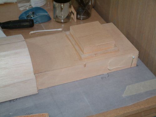
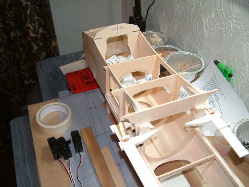
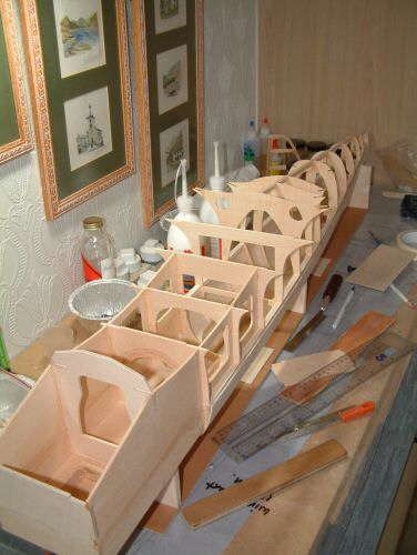
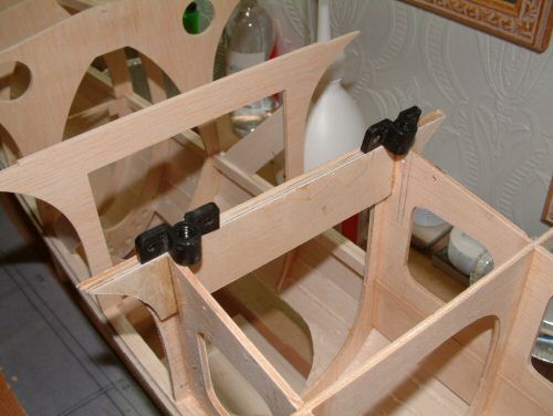
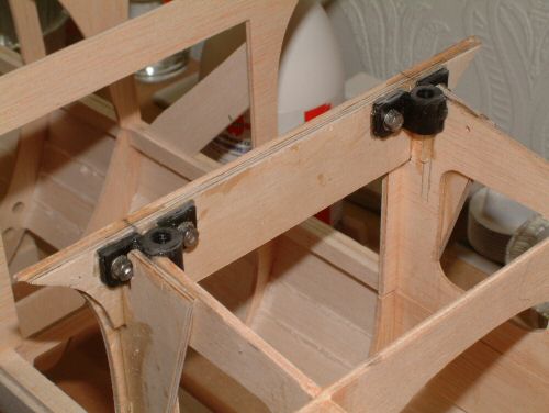
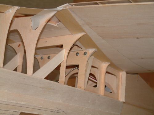
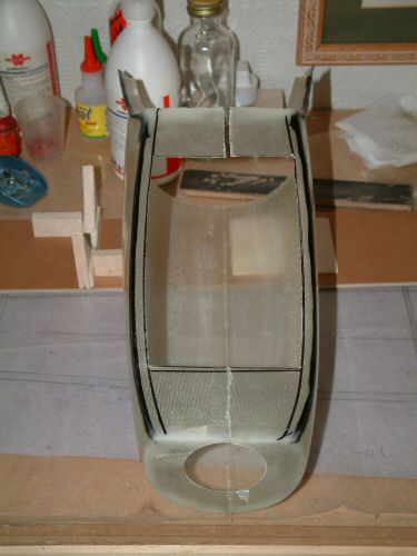
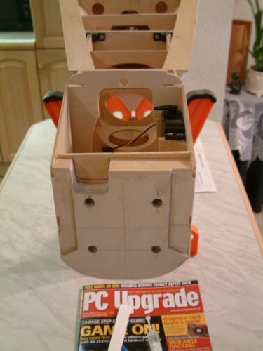
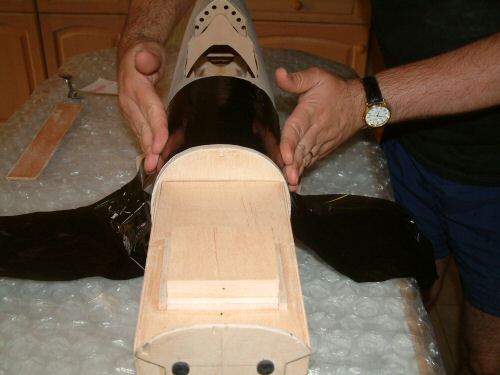
The parts are going together really well and it is time to check over two things before I continue. Pic 1. shows the cockpit parts trimmed and test fitted. I have also cut the exact line of the cockpit entrance from the fuselage. Pic 2. the stabiliser was test fitted to ensure a good fit. I found it necessary to sand from the front of the mounting for a good level fit. Pic 3. shows the the top former F7 in position which I have installed a small box 20mm deep so that it provides additional space for the servos behind the firewall. While I have sanded the fuselage, I have not done a final sanding to fully smooth the shape. This will be done immediately prior to glassing. Pic 4. Now moved to building the underside of the fuse and it begins by completing the box section at the front of the fuselage, dry assembled and then glued together before fixing to the fuselage. A good tip is to cover the fuselage with cling film and to glue the box section on the fuse to ensure everything lines up. Former F20 the firewall and F21 which holds the wing dowel were replaced by more solid ply and the hollow of F21 reshaped to accept the fuel tank. One annoying thing is the position of the holes for the wing dowels. Firstly wing construction only has the one dowel positioned about 15mm above the leading edge of the wing. The wood kit positions the dowel at the leading edge. This will be corrected later. Pic 5. shows the remaining formers F25 to F34 installed. As with the top of the Crutch spar some formers were not wide enough to bridge the gap. F29 to F33 all required adjustment from between 0.5mm to 2.0mm. Once installed the spine strip was installed quickly to give some rigidity to the structure. Pic 6. Shows the required location of the wing mounts. Having built the wing for fitment to the glass fuselage I am committed to making the fuselage fit to them. Test fitting the wing onto the fuselage gave a very good fit with only minimal sanding to achieve a perfect seating. The alignment of the wing to the fuselage was checked and was perfectly square. The mount hole positions were noted and are roughly where seen in the picture. I will be mounting the plastic nuts to the former F24 unlike the plans which mount from the sides of the box section. I have already installed a reinforcing strip of ply visible in the picture. Some of the box will need to be cut away for the fitment, and once located a modified F19a will be installed to reinforce the joint. |
 |
 |
 |
 |
 |
 |
| 1. Click to enlarge | 2. Click to enlarge | 3. Click to enlarge | 4. Click to enlarge | 5. Click to enlarge | 6. Click to enlarge |
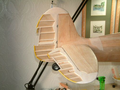
Pic 1. Shows the installed Wing mounts and former F19a fabricated out of strong ply. The threads literally sit on the inside edge of the box section. If you are building a wood fuse, make sure that you position the holes that bit closer together. My mounts are 112mm centre to centre. Pic 3. The first pair of 1/32" formers are installed with a sheet of 3/32" balsa down the centre. I soaked the balsa in warm water before starting to make it more flexible. I also used some cast iron weights to hold the sheet in place, hence the rusty spots! Pic 4. the wing strips are glued and then allowed to set with the wing in position to ensure a good fit. The glass cowl was delivered 15 July. Construction can now continue. |
 |
 |
 |
 |
 |
 |
| 1. Click to enlarge | 2. Click to enlarge | 3. Click to enlarge | 4. Click to enlarge | 5. Click to enlarge | 6. Click to enlarge |
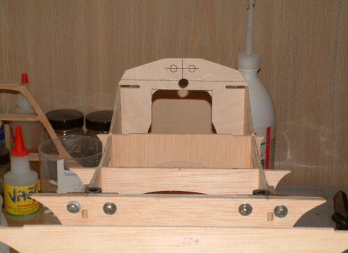
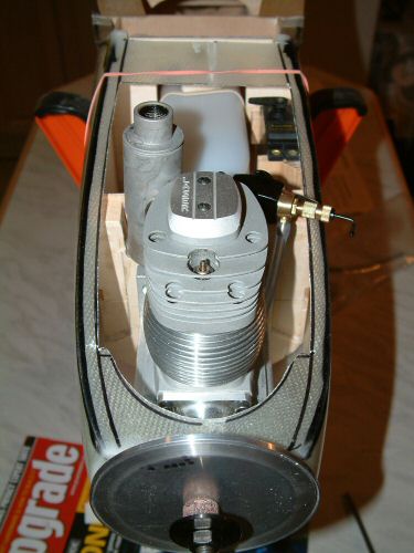
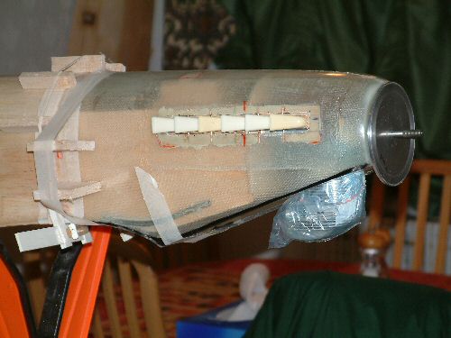
| Pic 1. I continued the assembly by making a mount for the tail wheel. The housing will be a detachable unit making replacement easy should it be necessary. Pic 2. Installed component in position, which will be retained by 2 screws at final installation. A a dummy wheel post will be added later. Sheeting continued using flexible balsa cut approximately to size, soaked (if required) and glued with the Thixotropic Polyurethane wood glue. The large fillet over the wing was particularly difficult to follow, and was completed with a piece bridging each former. Pic 3. Shows the completed rough planking. Pic 4. after the first coarse sanding and installation of the cowl after trimming F21 as mentioned earlier. Before the final sanding I will fill the obvious blemishes with lightweight filler. Pic 5. shows the firewall cut and spaced to accommodate the exhaust. The thickness of the firewall is 2 sheets of 4mm strong ply and then a sandwich of 10mm balsa and light ply to make the hollow for the exhaust. This only fits to just below the position of the first engine mounting bolts. The wall was reinforced with some triangular hard wood fillets on the inside. Pic 6. shows the installed engine, cowl, fuel tank and throttle servo. Nice fit though I say it myself. The hole for the fuel tank has not yet been cut. |
 |
 |
 |
 |
 |
 |
| 1. Click to enlarge | 2. Click to enlarge | 3. Click to enlarge | 4. Click to enlarge | 5. Click to enlarge | 6. Click to enlarge |
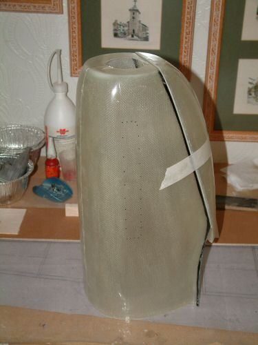
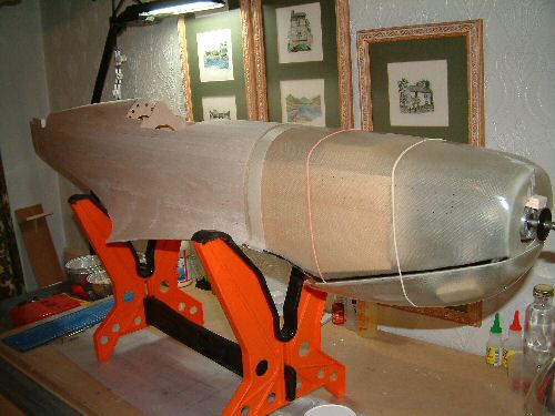
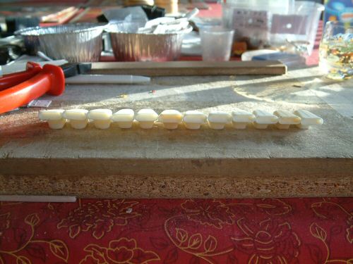
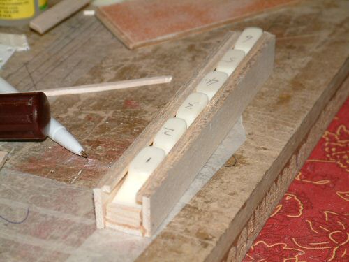
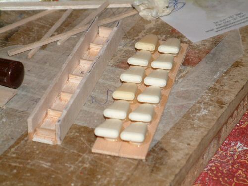
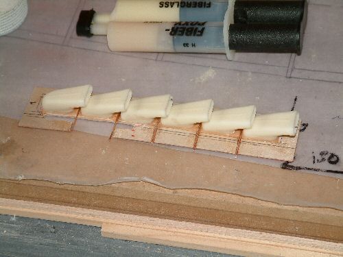
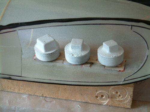
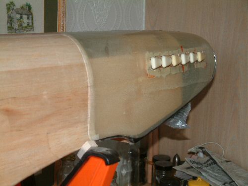
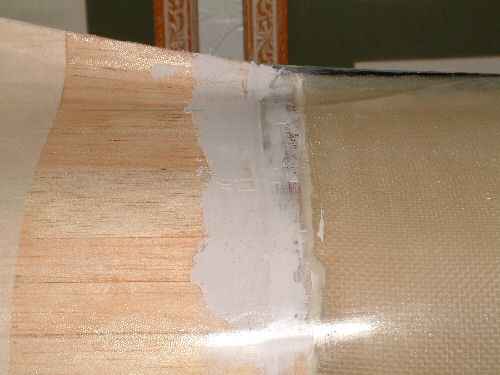
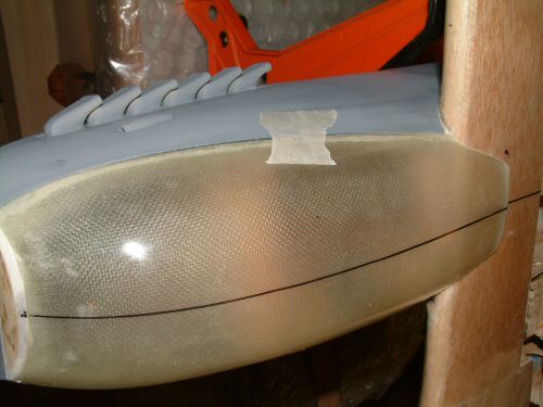
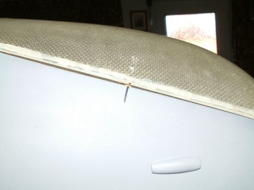
Pic 1. Using a thin coloured plastic film stretched over the fuselage I can check the smoothness of the sanded planks. This helps to assess the profile with a consistent contrast. Pic 2. With the final sanding completed I begin the glass cloth process. Never attempted this before so I was a little apprehensive at the start, but soon realised there was nothing to be afraid of. I am using SP Epoxy resin and SP113 Lightweight glass cloth. The fuselage will be covered in 3 parts. First the underside, then the 2 sides, overlapping at the top. Pic 3. The pipes looked fine, but they were all trimmed to a different height, so I lined them up and marked them 1 to 6 largest to smallest to make 2 similar sets. Pic 4. I fabricated a jig to hold the exhausts in position while I sanded the bases level. Pic 5. I then applied a strip of light ply with epoxy while the pipes were still in the jig. Once removed from the jig the completed exhausts all sit in a perfect line. Pic 6. I applied a sheet of 1/32" ply to the back and then grooved the ply between each pipe. I added a small length of copper wire and held it in position with cyano. These vertical bars are easily seen on the genuine article so it just adds a spot of realism to the finish. You will also notice I have cut a hole in the wood just below the first 3 stacks, this is hoped to add a little extra venting for the engine. |
 |
 |
 |
 |
 |
 |
| 1. Click to enlarge | 2. Click to enlarge | 3. Click to enlarge | 4. Click to enlarge | 5. Click to enlarge | 6. Click to enlarge |
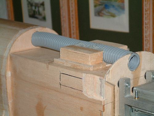
Pic1. To assist in the cooling I have installed a flexible tube flush with the firewall. This will feed into the wing later to draw air from the engine. Pic 3. They were then glassed in position with a strip of glass bandage and Epoxy. I also ran a narrow strip down the top side to add some rigidity to the structure. Pic 4. The test fitting of the cowl before final installation. Pic 5. The point of no return. Fitted in position with a variety of materials! Epoxy resin, Thixotropic Polyurethane, and rubber all deployed in the fixing. The foam is used just to add a little anti vibration protection. Pic 6. Using a "putty" glass filler smeared a film over the joint to begin the process of removing the joint. |
 |
 |
 |
 |
 |
 |
| 1. Click to enlarge | 2. Click to enlarge | 3. Click to enlarge | 4. Click to enlarge | 5. Click to enlarge | 6. Click to enlarge |
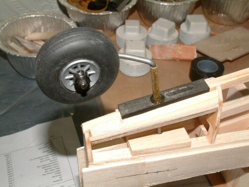
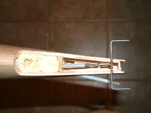
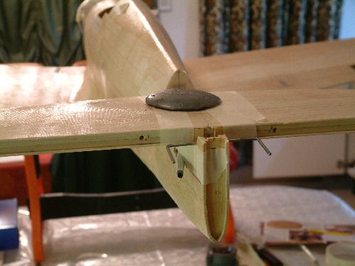
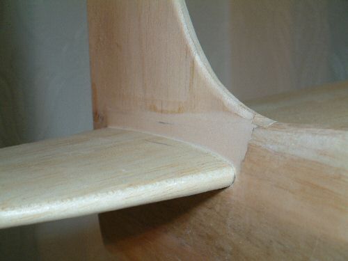
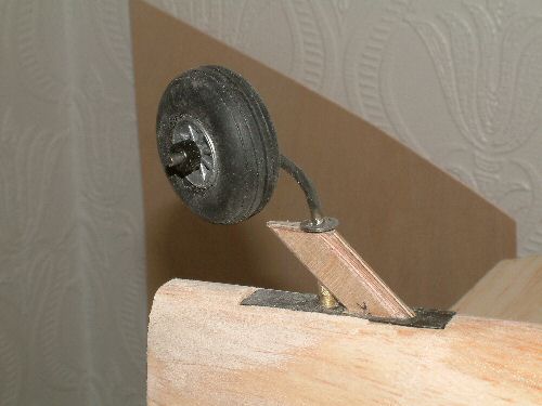
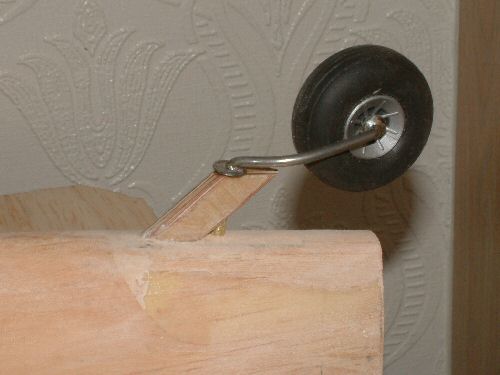
It's time to fit the rear end to the fuselage. Lightweight tube rods will be used to connect the rudder and elevator. Pic1. shows the control horn in position. Fabricated from wire and brass bar to connect the clevis to. This joint needs to be silver soldered to ensure it will be strong enough. Solder will not do! The rudder rod is also installed before making a fixing with epoxy, and then spraying in a controlled amount of foam filler. This will ensure that the 2 rods will not rub too much or vibrate. Pic 2. The elevator is installed with 12 minute Epoxy ensuring correct positioning. Pic 3. The fin is installed followed by a small fillet of balsa, before blending in with lightweight filler. Pic 4. Filler sanded to shape. I think I will need to see what this looks like after the first primer coat in applied to be fully happy with the bleeding from fin the stab. Pic 5 .The tail wheel post was formed from 3mm ply and then laminations of 1/32" ply to surround the brass baring and sanded to shape. I decided to install the wheel permanently rather than with fixing screws as a weight saving. Pic 6. The finished item prior to a patch of glass cloth to prepare for painting. |
 |
 |
 |
 |
 |
 |
| 1. Click to enlarge | 2. Click to enlarge | 3. Click to enlarge | 4. Click to enlarge | 5. Click to enlarge | 6. Click to enlarge |
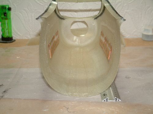
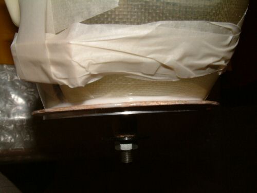
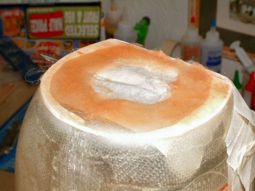
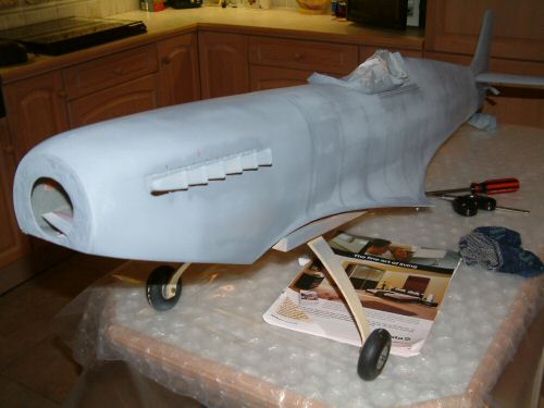
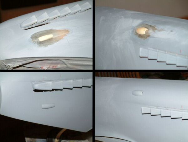
Pic 1. The rudder and elevators were test fitted to see that everything would be OK in final assembly before clothing the surfaces. Pic 2. The spinner is not a uniform distance from the fuselage, so I installed a sandwich of 1/16" balsa between the spinner and the fuse and flooded the area behind with Epoxy / Micro-balloons mixture. Pic 3. When the Epoxy was set I in filled the remainder with glass cloth. This added some much needed rigidity to the bulkhead. Pic 4. Time for the first of several primer coats. I have made a wheel mount for an old undercarriage I had spare. This will help with the painting process and later when the model is in transit. This first spray has highlighted a few areas where there will be some sanding and filling. All in all it looks OK. Pic 5. The 2 vents on the front engine cowl were made from Epoxy and Microballoons mixture moulded in the supplied plastic parts. These were hollowed out and installed with 5 minute Epoxy. The picture is sectioned to show the as installed and after priming. Pic 6. First test fit of the lower cowl after trimming the rear section to make room for the wing. Not too bad a fit but some filler will be needed to make it a snug fit. Final fitting will wait for the wing to be at final prep stage. |
 |
 |
 |
 |
 |
 |
| 1. Click to enlarge | 2. Click to enlarge | 3. Click to enlarge | 4. Click to enlarge | 5. Click to enlarge | 6. Click to enlarge |
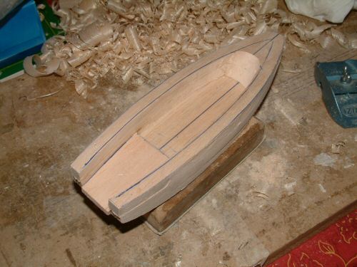
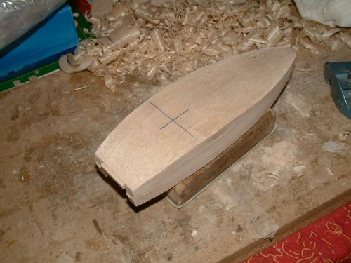
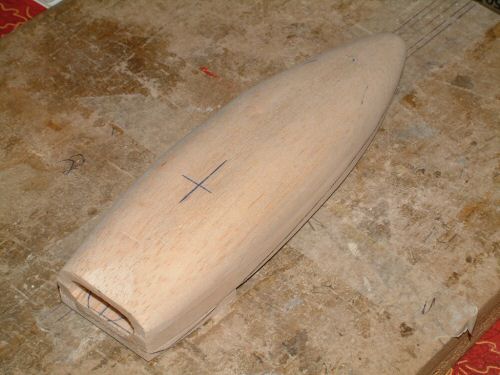
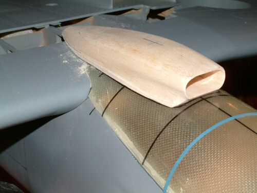
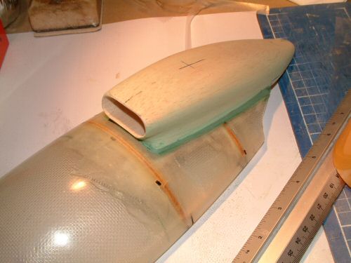
After a short pause I am back with the front lower cowl. Pic 1. One of 6 locating dowels installed into the fuse with locating holes in the cowl. It also highlights a little gap on the face edge which will require some attention later. Next I turned my attention to the air scoop. The provided scoop is for an early MKXI and I therefore have to fabricate one myself. I started with getting the basic shape from the plans which show the outline of the later scoop. Pic 2. After looking at a few pictures in reference books I began cutting my design from 3 sheets of 10mm balsa to get the basic shape. An insert of 4mm balsa at the front can be seen in the picture, this will for the front lower edge later. Pic 3 . Another 10mm top sheet and an inlay of 4mm as the bottom to form the front top edge. The outline curve was then shaped with a block plane. Pic 4. Sanding, sanding and more sanding brings the basic recognisable shape to the scoop. Pic 5. A test fit looks OK and the careful and slow process of sanding to fit to the cowl begins. Pic 6. Inside the cowl 2 formers have been glassed into position to add some rigidity to the section before installation of the scoop. I used Fibre Poxy for the joint and modeling filler to smooth the edge off. |