
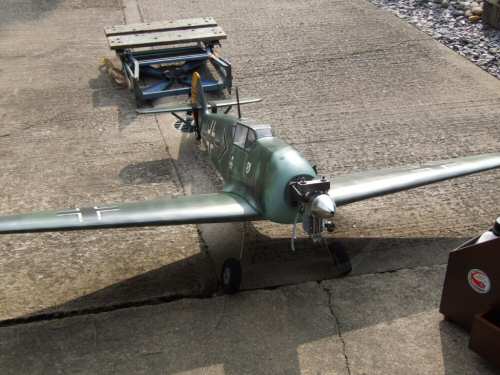
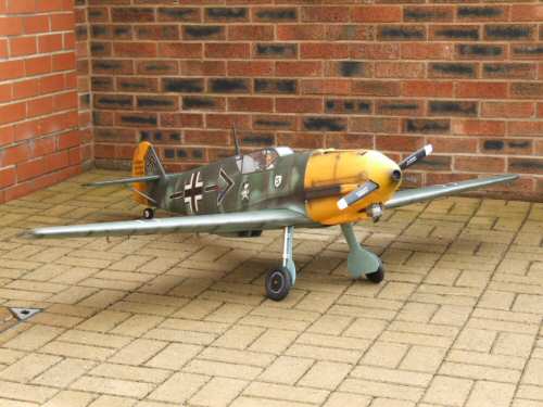
YT International BF109 - Final FixingIt's time to bring it all together and make a finished aircraft. In this section it is mainly assembly rather than construction, with some finishing touches to the paintwork . . . |
 |
 |
 |
 |
 |
 |
| 1. Click to enlarge | 2. Click to enlarge | 3. Click to enlarge | 4. Click to enlarge | 5. Click to enlarge | 6. Click to enlarge |
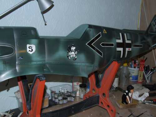
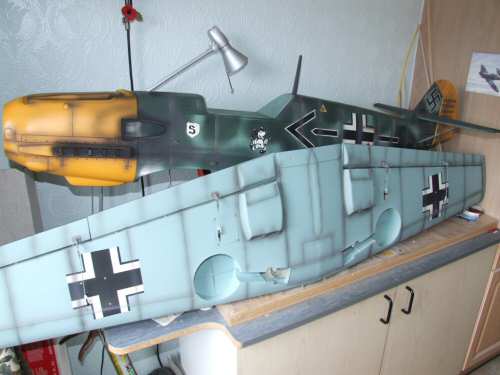
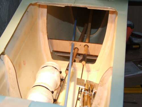
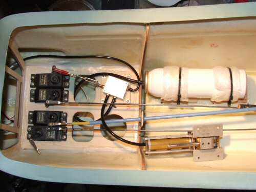
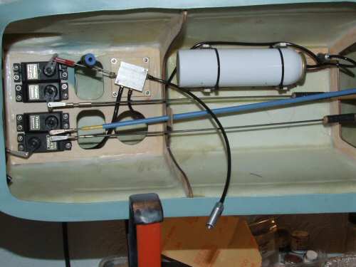
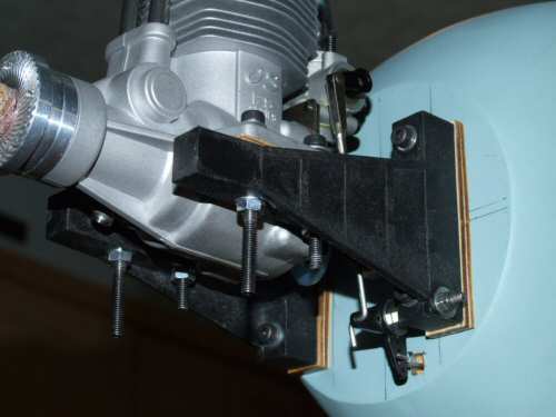
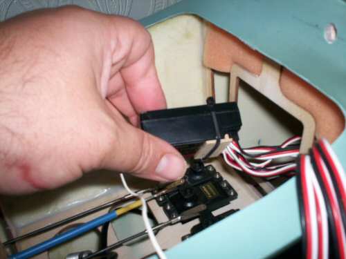
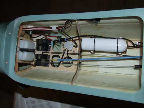
Pic 1. I am not going to do too much weathering, just dirty it up a little. First I airbrushed silver to the shadow side of each former. Pic 2. I then sprayed a blend of black, white, and brown to give a dirty appearance to the formers on the fuselage and the drawn panel lines on the wings. I will be scuffing it with a little "OO" wire wool before fuel proofing. Pic 3. Shows the installation of the push rod guide set slightly further back to that specified in the instructions to prevent snagging with the heat shrink on the dowels. Notice also the plastic "snake" routed for the tail wheel. As I mentioned in the Fuselage section, 3 supports were used to support the snake, the middle one seen here. I find Zap-a-da-pa-Goo II most effective at securing these rods. Pic 4. Shows the installation of the air tank, servos, and the air control valve. The picture was taken while I was testing this part of the installation for leaks. Notice the retract arm fully retracted under pressure. It will remain like this overnight to see if it has any air leaks. The filling line runs to a standard Robart filler valve which acts as a secondary backup for the none return valve in the air control valve assembly, which has a reputation for failing. Slight issue with the Robart connection as it uses narrower gauge tubing to the YT system. I have however manage to get the narrower Robart tubing to fit the YT connections with a little warm water. Pic 5. After some considerations I changed the layout a little and added a Robart Pressure gauge which will be visible inside the cockpit (this also required use of the narrower tubing). Pic 6. Installing the engine with the throttle connection clearly visible. I have never used a bell crank to control a throttle before and always struggled to get a nice connection. This works very well and I will certainly consider it again in the future. |
 |
 |
 |
 |
 |
 |
| 1. Click to enlarge | 2. Click to enlarge | 3. Click to enlarge | 4. Click to enlarge | 5. Click to enlarge | 6. Click to enlarge |
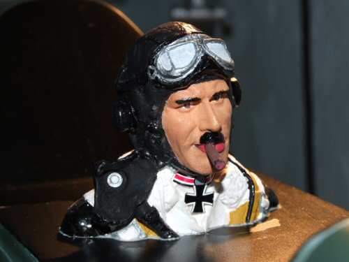
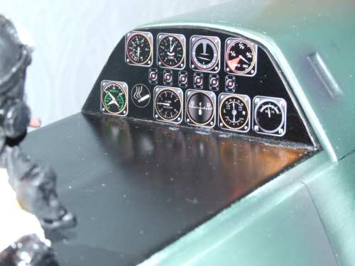
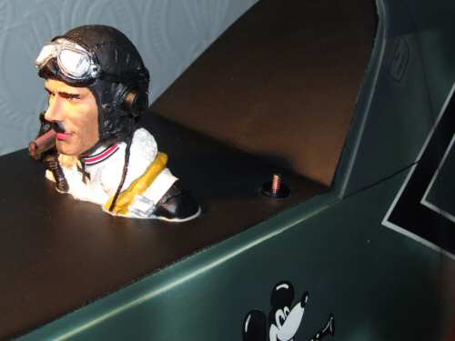
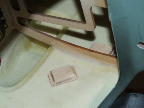
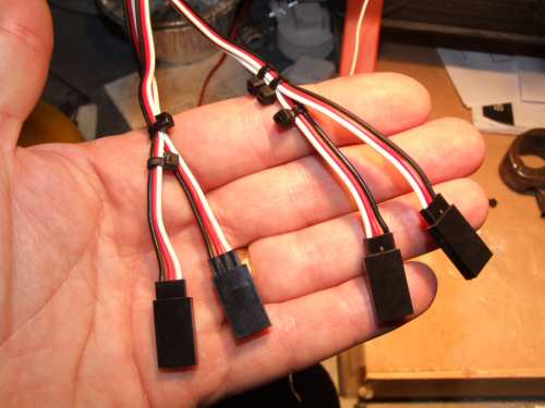
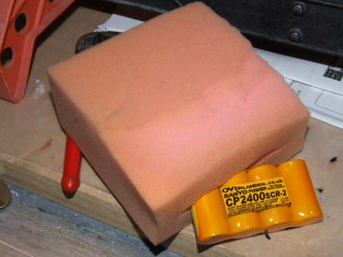
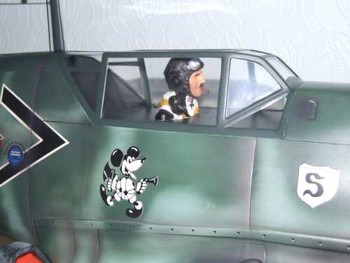
Pic 1. My Pilot has been cut to size and painted to look a little more German. Galland was reputed to be a heavy cigar smoker so I fabricated a "smoke" for him and added the moustache to make him a little more in character. The pilot was fixed in position using epoxy onto a roughed up surface that exposed the glass fibre to ensure a good key. Pic 2. Not too much on the dials, I just cobbled together some images I have previously produced for my Spitfire and made them fit. Note the representation of the cigar lighter Galland was reputed to have in his 109E. That's the end of the fun! Pic 3. Another view of the pilot, this time the pressure gauge is visible toward the rear. . . still holding it's pressure! Pic 4. The cowl is held in position with a series of 6 cross head screws. I have made my own ply blocks to epoxy in the required positions before drilling the 1.5mm holes. Pic 5. Servo setup time and I use the following channel assignments. Ch1:Aileron R, Ch2: Elevator, Ch3:Throttle, Ch4:Rudder, Ch5, Retracts, Ch6: Aileron L, Ch7:Landing Flap R Ch7: Landing Flap L. All of the wing servos need an extension and therefore some form of identification to make hookup easy. I use a simple rule every time for this: Ailerons held together with one tie and the right channel has an extra tie, Flaps use 2 ties to hold the wires together and the right channel has an extra tie. I always allocate the lowest number channel to the right wing too which makes it easy to follow. Pic 6. I am using my Overlander 2400mAh battery for this model. Wrapped in plenty of foam it will sit snug under the fuel tank and as far forward as possible. |
 |
 |
 |
 |
 |
 |
| 1. Click to enlarge | 2. Click to enlarge | 3. Click to enlarge | 4. Click to enlarge | 5. Click to enlarge | 6. Click to enlarge |
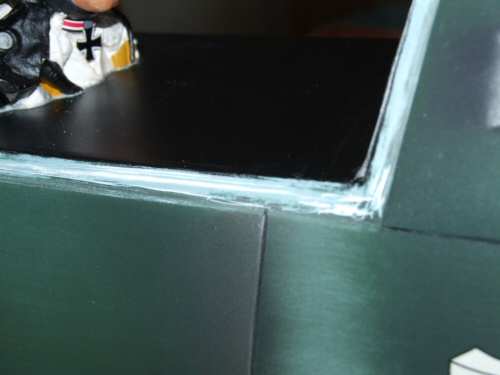
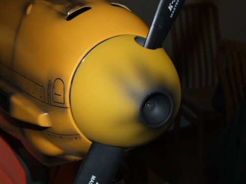
Pic 1. The receiver connections are held in position by a few small ties and scraps of ply bridging the gap between the connectors and the top of the receiver. That done the receiver was wrapped in foam and positioned on the port side of the fuel tank resting on the battery foam (visible in the background). Pic 2. Next I decided to install the cockpit as I was going away for a few days. Rather than use screws to secure the cockpit I cut the contact surface back on the fuselage to give a good key. I also scuffed the plastic cockpit surfaces that would be in contact with the fuselage with a Dremel very carefully so as not to over heat the plastic or sand too much away!! If you don't know what I mean by this try using your Dremel sanding disk on a scrap of plastic before you work on the actual cockpit!! Pic 3. The cockpit was glued in position with cockpit adhesive. The molding of the cockpit was that good it only needed a small weight on top of the frame to hold it down while the glue dried over the next 48 hours. Pic 4. Next the radio wire was fabricated from black elastic and secured to the fin by a small loop of copper wire epoxied into the surface. At the other end it was tensioned by a retainer in the fuselage. The radio mast itself is installed by looping the elastic through a copper ring on the mast which enables quick installation at the flying field. Pic 5. I painted the spinner cone yellow today and added some black sooty marks to rough it up. A little upset that I did not attempt to colour match the yellow beforehand, but I have written a note to self reminding me of the need to colour match before such undertakings again! Pic 6. The fuel tank was checked once again to ensure it was air tight before I installed it into the fuselage. To add some protection from it rubbing on the engine bolts I added a foam cushion around the neck of the tank. The foam ring was taken from a spindle of DVD's so its a free and very practical accessory!! I installed the tank carefully so as to not catch the foam of the battery and the receiver. |
 |
 |
 |
 |
| 1. Click to enlarge | 2. Click to enlarge | 3. Click to enlarge | 4. Click to enlarge |
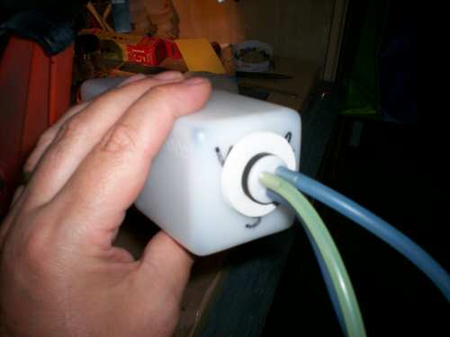
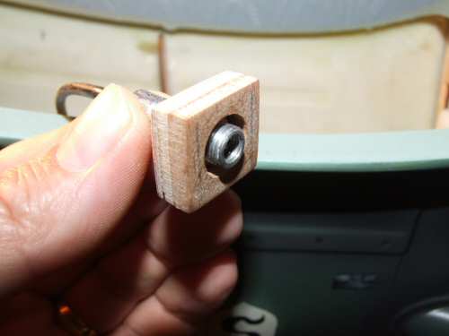
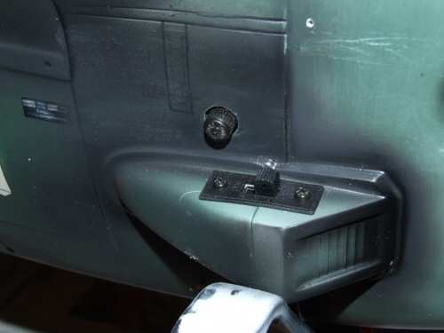
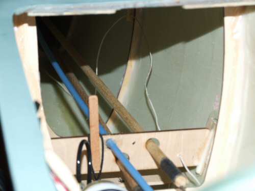
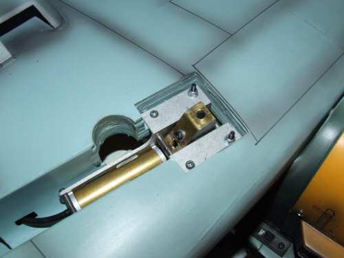
Pic 1. The air filler valve has been upgraded to a Robart unit as I have heard stories of the none return valve in the supplied YT units failing after short service. I made a small housing to mount the valve from laminations of ply before using epoxy to hold it in position inside the fuselage wall. I adjusted the fitment so that the metal valve was just proud of the surface of the fuselage. To protect the valve from any debris flying in there during flight I have installed a standard dust cap. Pic 2. I decided to install the air valve close to the air intake of the 109 along with the power switch which fits nicely within the confines of the air housing. Pic 3. Everything is now installed and in position. Note the air valve housing on the side wall and the routing of the aerial. Pic 4. The aerial wire installs down some guide holes drilled into the framework or 1/32" ply (just visible in the top of the picture) glued to the framework. Also shown is the peg retaining the antenna elastic. |
 |
 |
 |
 |
 |
 |
| 1. Click to enlarge | 2. Click to enlarge | 3. Click to enlarge | 4. Click to enlarge | 5. Click to enlarge | 6. Click to enlarge |
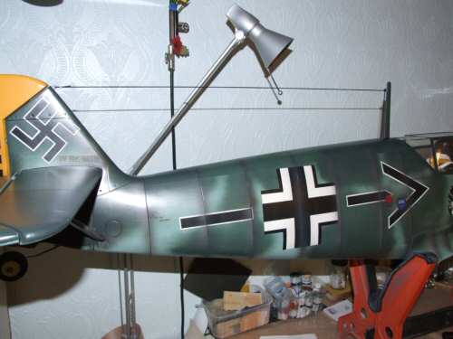
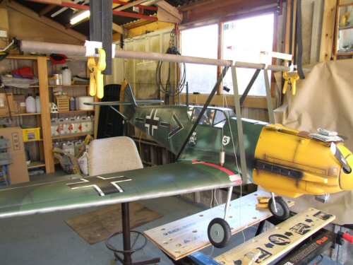
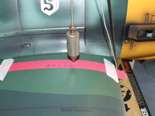
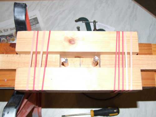
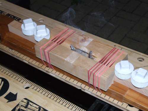
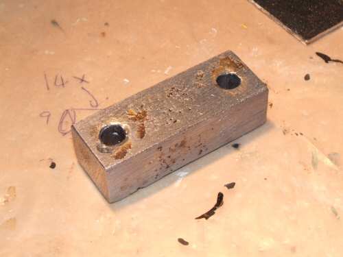
Pic 1. Time to balance the model. The instructions tell us to balance the model at 116mm from the leading edge however, there is much discussion and general agreement on RC Universe and RCMF UK for the balance to be between 95mm - 100mm. I have swung the model in it's cradle and added 670g (just short of 1½ lb) to the area where the front engine mounts are. Pic 2. Final checks are conducted with the wheels up. Pic 3. I plan on starting with too much lead and reducing the ballast until the desired CG is achieved. With the 670g of weight up front the balance is just forward of the 90mm mark. With losses in the melting process I should have enough spare to make the balance at the 95mm to 100mm mark which I estimate to be about 550g (1lb 4oz). Pic 4. The mould is made from scraps of softwood I have in the garage. Two dowels are positioned inside the mould and will form the mounting points to the front engine mounts. Pic 5. The lead cooling just after pouring. Pic 6. The final result after a little cleaning up exercise. |
 |
 |
 |
 |
 |
 |
| 1. Click to enlarge | 2. Click to enlarge | 3. Click to enlarge | 4. Click to enlarge | 5. Click to enlarge | 6. Click to enlarge |
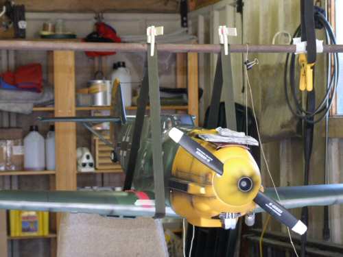
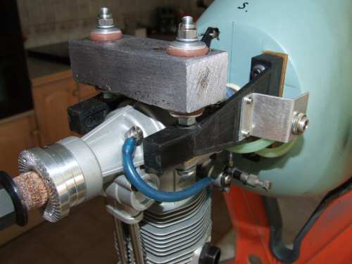
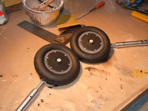
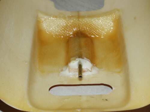
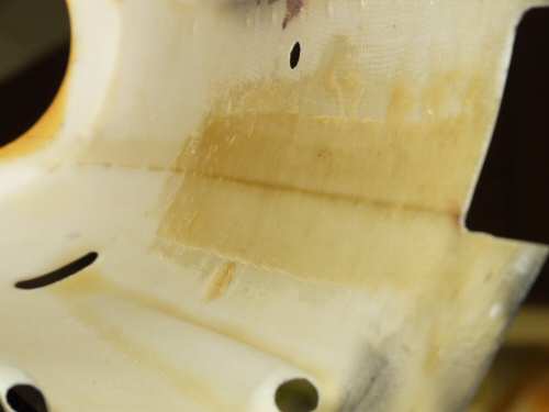
Pic 1. Managed to fully install the engine and mount the lead block on the front bearers. As lead is a soft metal I have sandwiched the weight between 2 rubber mounts to prevent any deformation of the lead from engine vibration. Also visible in the picture I have installed a Du-bro filling valve that will sit just behind the cowl accessed via a simple hole. Pic 2. Before installing the wheels I decided to paint them black and put a few highlights on. During installation I stripped the threads on the shafts when locking down the nylock nuts. This happened with very little force so I decided to fabricate new shafts cut to exactly the right size. Collets were soldered to the ends of the shaft and are clearly visible in the picture. I used a washer on each end of the wheel shaft and lubricated the rolling surfaces with silicone grease. Pic 3. The vent pipe for the fuel tank will drain from the bottom of the cowl through some brass tube. This was glassed into position resting on a balsa block. Pic 4. While I had the resin mixed I added 2 strips to the inside wall of the cowl which were looking particularly weak, one side displaying a small crack as confirmation. Pic 5. While the resin cured I decided to test the engine in the model. I always conduct the first test un-covered because you can see if everything is OK. I experimented for a while and as a conclusion I realised that the OS FS120 Pumper really needs 10% nitro for good smooth performance. Pic 6. I did not like the use of all screw mounts for the retract mechanism so I swapped a front and rear set for 3mm bolts. I would have swapped the other 2 but that would have compromised some supports behind the ply beams. |
 |
 |
 |
 |
 |
| 1. Click to enlarge | 2. Click to enlarge | 3. Click to enlarge | 4. Click to enlarge | 5. Click to enlarge |
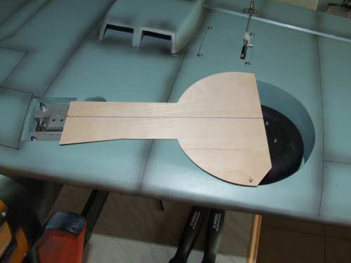
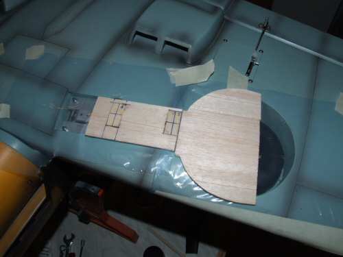
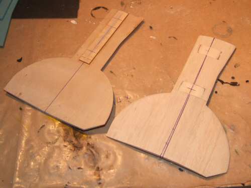
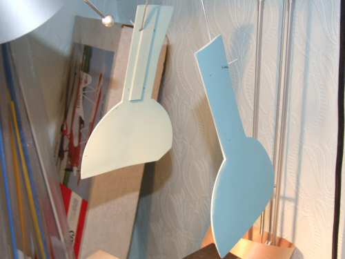
Pic 1. I only have 24 hours before this model is flying so I am quickly making the wheel covers. I am not using the stock covers as they are not suitable in my opinion. I start with the outline in 1/32" ply. Pic 2. I then add 1/8" balsa with some 1/8" ply where the OLEO braces will be located. While the glue for the lamination dried the whole thing was under tension using weights and tape to make the cover adopt the profile of the wing curvature. This shot was taken after it was all dry. Pic 3. On the back plate a 1/8" ply spacer was added to permit comfortable spacing for the cover, and sanded to shape on the face side. Pic 4. I glassed the front face and force cured it under a lamp before quickly sanding and painting the surfaces. Normally I wait 24 - 48 hours for this but that is not workable. Pic 5. The covers were retained with strips of tin working like a brace round the OLEO. All finished and ready to play!! |