
 |
 |
 |
 |
 |
| 1. Click to enlarge | 2. Click to enlarge | 3. Click to enlarge | 4. Click to enlarge | 5. Click to enlarge |
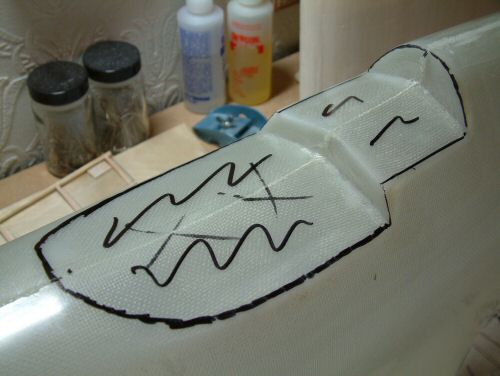
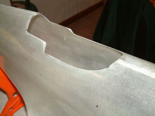
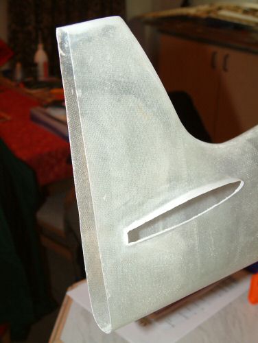
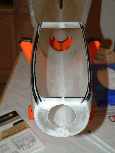
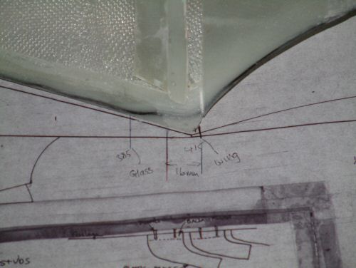
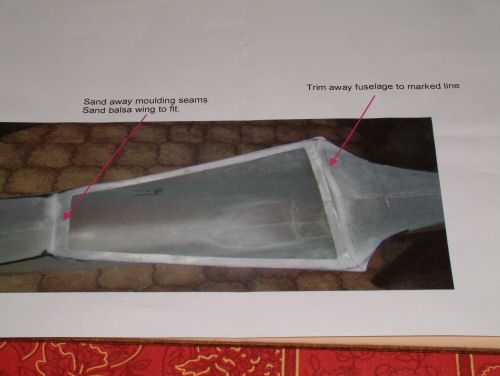
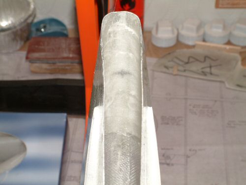
Now the wing is coming along I have begun some preparations on the glass fuselage. Pic 1. shows some marking up before attacking the job with my trusty Dremmel. Pic 2. the finished result roughly sanded. Pic 3. The tail plane slot cut and the rudder root straightened. The tail plane will require opening up later to accept the stab. For now I will leave it as it is. Pic 4. The front underside is opened up to facilitate access to the engine bay and the electrics when they get installed. A hole is made for the spinner. Pic 5. Measuring up my wing and the gap in the glass there is a clear problem with the fit. On the plans the centre section is 415mm deep. My wing is 418mm deep and the glass fuselage is only 402mm to the inside of the ridge. I have cut the rear of the housing to enable the wing to fit in. This was done in 2 sections the first piece shown in the picture roughly where it was cut from. I was then more able to judge the second cut to permit a snug fit. I was not very happy with this situation as there was a significant amount of glass re-enforcement in the root which is now not going to be available. I will have to make a new root when installing the former, which will have to be modified to fit round the wing. |
 |
 |
 |
 |
 |
 |
| 1. Click to enlarge | 2. Click to enlarge | 3. Click to enlarge | 4. Click to enlarge | 5. Click to enlarge | 6. Click to enlarge |
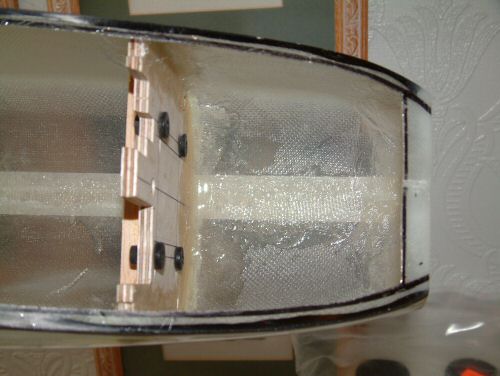
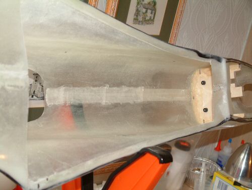
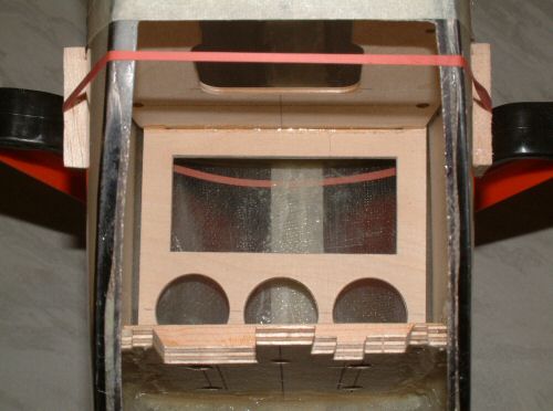
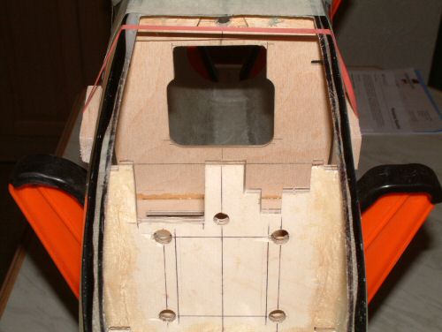
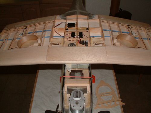
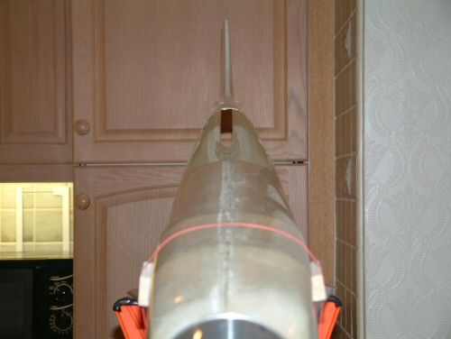
I now need to fit the wing into the fuselage to get the fitment correct and to align everything up. To do this I am going to get all the formers fixed in position so there can't be any mistakes with formers moving. Pic 1. shows a picture supplied with the retract servo confirming that I had cut the fuselage in the correct area. I can only imagine the inclusion of this sheet in the box following a short conversation with Jim at Mick Reeves Models. Why this was not supplied with the fuselage I have no idea. Pic 2. After sanding the inner surface of the glass and wiping with Acetone to get a good key I fitted the firewall in position using some glue called "Fiber Poxy". Stinks to high heaven and goes off very quickly. I installed the engine mounts, engine, and the spinner to make sure it all aligned up. When dry I removed the engine and mount to access the area for glass reinforcement. I also ran some glass round the inside of the spinner area to add some rigidity to it. Note also the cut outs in the firewall to make room for the exhaust and the carb. You will see later what I plan for this later. Pic 3. After sanding the external moulding marks to remove blemishes the joints were in most places very thin. In some places there were visible gaps! so I decided to run some glass down the joints to stiffen them up. Pic 4. Added sandwich of 2 cloths in the area where the tail wheel is to be mounted (you have not seen my landings!) Pic 5. shows the installed parts. The rectangular cutout will take the rudder and the elevator servo carries an plywood beams, while the throttle servo will be mounted on a sub assembly above and to the side of the fuel tank (as we look from the bottom). Pic 6. another view to show F2 in position. Note the enlarged hole to accept the fuel tank. The Reeves plans show the fuel tank installed higher in the model to accommodate a 2 stroke, but for the Laser 4 stroke I need to install as low as possible, hence the cutout at the bottom. I will be installing a Kavan 12oz fuel tank which should give over 10 minutes at full throttle. Former F2 did not fit too well and required some encouragement with 180 grit lets say. |
 |
 |
 |
 |
 |
 |
| 1. Click to enlarge | 2. Click to enlarge | 3. Click to enlarge | 4. Click to enlarge | 5. Click to enlarge | 6. Click to enlarge |
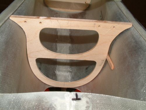
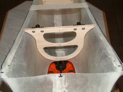
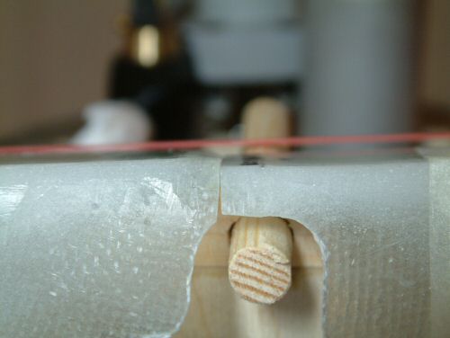
Finally the wing former support F3 is installed. I tried to get this piece to fit snug but to no avail. Pic 1. Shows the gap. I played with it for 2 hours lifting the wing on and taking it off trying to get the thing to align. I eventually gave up and fabricated my own from 1/8" ply. Pic 2. Not CNC cut but my trusty Jig-Saw and Dremmel came in a good second best. Replacement F3 in position with mounts installed. I made the reproduction of the former using PowerPoint and then increased the height and width slightly. A few dry runs with the dowel in the front of the wing and it was time to install. Pic 3. I mounted the wing in position while the Fiber Poxy glue set. Pic 4. Shows a front on view. Is it me or is there some twisting in there? Pic 5. the joint at the front leading edge of the wing rests here and retained by the dowel. There was 3mm drift here before I cut it during installation of F2 to reduce the ridge. Pic 6. shows the joint after sanding the ridge off. |